
Conducting a Fire Flow Test
Background
It is very important for many reasons that fire departments know, understand, and use the proper procedure when conducting a fire flow test to determine the amount of water available in a given fire hydrant and water main for fire protection purposes. First among these reasons is that the information is needed for community planning and tactical firefighting purposes. Engineers, architects, sprinkler contractors, and commercial property developers use this information to design fire protection systems. Fire officers and city planners need to know if there is adequate water available to fight a fire in a given building. Also, the Insurance Services Office (ISO) uses fire flow information when determining the credit available for water supply under Section 600 of the ISO Fire Suppression Rating Schedule (FSRS).
Prior to the adoption in Tennessee of the current edition (June 2012) of the FSRS on July 1, 2013, ISO representatives would witness fire flow tests conducted by community officials as part of the process of establishing the community’s Public Protection Classification, more commonly called the ISO Rating. Under the new FSRS, ISO may witness flow tests or may ask the community to provide fire flow information for selected properties at risk in the community. ISO then uses the flow test information when determining the credit for water supply. ISO may elect to witness one or more fire flows, but if the field representative does not witness the flow test, the information provided by community officials is used.
When assisting communities in preparing for an ISO evaluation, MTAS has observed that some communities use the single fire hydrant flow test method to collect the data needed. The single fire hydrant flow test is inaccurate for providing a true reading of the water available for firefighting purposes. Neither the National Fire Protection Association (NFPA), nor the American Water Works Association (AWWA), recommend the single fire hydrant flow test method, and MTAS recommends that cities use the two (or more) hydrant flow test procedure to get the most accurate results.
Fire Flow Testing Overview
A fire flow test is the measurement of the normal operating pressure in the water mains under normal distribution-system flow conditions (static pressure), the pressure in the water mains when water is flowing during the test (residual pressure), and the flow pressure at the outlet (pitot pressure). A cap gauge is required to measure the static and residual pressures, and a pitot gauge is required to measure the flow pressure from the flow outlet. In addition to these pressure readings, the size and the internal shape of the opening flowing water (i.e. the coefficient of the discharge), and the number of openings flowing are required. All of this information is used in two formulas to determine the amount of water flowing during the test and the amount of water available at 20 psi residual pressure. The amount of water available at 20 psi residual pressure is known as the available fire flow, and this is the flow that ISO uses when evaluating the water system.
Performing Flow Test Calculations
Before discussing the procedure to use to conduct a flow test, we are going to cover the two formulas used and how to perform the calculations, as this knowledge will illustrate the need for a two hydrant flow test and the importance of following the flow test procedures.
The first formula is commonly called the Q formula. The formula is also known as the Freeman Flow Formula (after John R. Freeman) or the Underwriters Flow Formula. The Q formula determines the amount of water flowing during the flow test. The Q formula is:
Q=29.83 * C * d2 * √P * N
The components of the Q formula are:
Q the total gallons flowing during the test
29.83 this is a constant based on physical laws relating to water velocity, pressure, and conversion factors to provide a result in gallons per minute (gpm)
C the coefficient of the discharge (typically 0.90 is used)
d the diameter of the discharge opening in inches
P the pitot pressure reading at the discharge opening
N number of outlets flowing during the test
The C factor accounts for friction loss, and the value of C depends upon the configuration and type of opening present in the hydrant. This value is related to how smooth the inside of the discharge outlet is. Research has shown that a fire hydrant does not flow 100% of the water available in the hydrant due to turbulence that occurs within the barrel of the hydrant. All other factors being equal, a fire hydrant with a smooth discharge outlet will permit more water to flow than an identical brand and model hydrant with a rough discharge outlet.
The C values shown below are from the NFPA Fire Protection Handbook and IFSTA Water Supplies for Fire Protection and are suggested values for C. A typical flow test uses a single 2½” opening, which is adequate for an accurate flow provided there is a sufficient change in the static pressure.
The person conducting the flow test will need to determine the type of opening on the hydrant by reaching in to the hydrant and feeling the contour of the opening.
- Rounded – the discharge outlet does not protrude into the hydrant barrel and the opening is rounded over where the opening meets the barrel
- Square – the discharge outlet does not protrude into the hydrant barrel but the opening is square (90 degrees) where the opening meets the barrel
- Projecting – the discharge outlet protrudes into the hydrant barrel
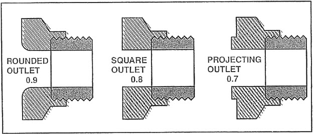
C factors for outlets of less than 4-inches in size and type are given below.
- Outlet less than 4" in size, smooth and rounded: 0.90
- Outlet less than 4" in size, square and sharp: 0.80
- Outlet less than 4" in size, projecting: 0.70
If it is necessary to use the pumper outlet (defined as 4-inches or larger) for the fire flow test, an additional factor is applied to the result to get the correct fire flow. This is because the stream from a large fire hydrant outlet is not entirely solid. To get an accurate flow, one first uses the Q formula to get the total water flowing and then applies a correction factor to the result. For example, if a 6 psi reading on the pitot gauge on a 4-inch opening shows that 1,050 gpm were flowing, this number must be multiplied by 0.84 to get an accurate result. Thus, 1,052 x 0.84 = 884 gpm. The suggested correction values when flowing large hydrant outlets are shown below.
| Velocity Pressure | Factor |
| 2 psi | 0.97 |
| 3 psi | 0.92 |
| 4 psi | 0.89 |
| 5 psi | 0.86 |
| 6 psi | 0.84 |
| 7 psi and over | 0.83 |
The second formula is the Hazen-Williams equation for calculating the amount of water available in the water main at a given residual pressure. The “industry standard” residual pressure used to calculate available water is 20 psi, as reducing the remaining pressure in a water main to less than 20 psi can cause damage to the water system and/or create backflow conditions. Finally, Tennessee Department of Environment and Conservation (TDEC) Rule 0400-45-01-.17(9) requires that water system be operated and maintained to provide minimum positive pressure of twenty (20) psi throughout the distribution system. Therefore, the available fire flow (AFF) is the amount of water expressed in gallons-per-minute available in the test fire hydrant when the residual pressure in the water main supplying the test fire hydrant is 20 psi.
The Hazen-Williams formula is:
AFF = Q(((S-20)0.54)/((S-R)0.54)))
Where:
Q the total gallons flowing during the test (from the Q formula)
S static pressure
R residual pressure
20 required residual
0.54 a constant used in the Hazen-Williams formula
Performing A Flow Test
Secure permission from the water purveyor before operating any value or fire hydrant on the water system.
Since a flow test will cause an increase in the flow rate inside the main, the test will stir up rust, scale, and sediment that is present in the main, which could result in “dirty water” complaints from water customers. The test will also increase the flow demand on the water system, which could set off alarms in the water plant or activate water flow alarms on fire protection systems. For these reasons the person conducting the flow test must always notify the local water purveyor before starting a flow test and notify the local fire department.
Care must be taken during the flow test to protect property and prevent damage. Water under pressure can damage lawns, flower beds, etc., and runoff can cause temporary flooding. The water stream may impede vehicle and pedestrian traffic. Flows made during freezing weather can cause ice to form. The hydrants must be opened and closed slowly to prevent damage from a water hammer. The hydrant must be in good working order and caps must be secured to prevent damage to the hydrant and possible injury to persons nearby.
An accurate flow test always involves a minimum of two fire hydrants. The first hydrant is called the test hydrant, and this is the hydrant used to record the static and residual pressures. This hydrant is located as close as possible to the property being evaluated. The second hydrant is called the flow hydrant and this is the hydrant used to obtain the pitot reading. The flow hydrant should be downstream from the test hydrant. For good results, the static pressure should drop at least 10 psi once the flow hydrant is open fully. If the static pressure does not drop by at least 10 psi it may be necessary to flow an additional hydrant or open a second cap. NFPA 291 section 4.3.6 goes further and states “To obtain satisfactory test results of theoretical calculation of expected flows or rated capacities, sufficient discharge should be achieved to cause a drop in pressure at the residual hydrant of at least 25 percent, or to flow the total demand necessary for fire-fighting purposes.”
The test procedure is as follows:
- Determine the best location of the two hydrants to use for the test. The hydrants should be as close as possible to the property being evaluated. The test hydrant should be the closest hydrant to the property, and the flow hydrant should be the next hydrant downstream from the test hydrant.
- Visually inspect both hydrants for obvious damage and/or defects. Do not use any hydrant that appears damaged or unsafe, and report such hydrants to the water purveyor for repair.
- Remove a 2½” cap from the test hydrant and attach an appropriate pressure gauge. Slowly open the valve on the test hydrant and allow water under pressure into the hydrant. Allow a few minutes for the pressure reading on the gauge to stabilize. This pressure is referred to as the static pressure and represents the water pressure in the water main as measured at the elevation of the hydrant outlet. Record the static pressure. Notify the crew at the flow hydrant to proceed.
- Remove a 2½” cap on the flow hydrant. Check and make sure that the discharge water stream will not damage property. If needed, use a diffuser or other method to protect property. Divert or stop traffic if needed. Determine the coefficient of the discharge outlet by checking to see if it is rounded, square, or projecting and record the type opening. Upon receiving the notification to proceed from the test hydrant crew, slowly open the hydrant all the way and create a steady flow of water from the outlet.
- Use a pitot gauge to measure the velocity pressure of the stream flowing from the hydrant. While the pitot pressure is being recorded, notify the crew at the test hydrant to take a second pressure reading and record the result. This is called the residual pressure. The residual pressure records both the domestic and fire flows occurring in the water main. After confirming that the crew at the test hydrant has recorded the residual pressure, slowly close the flow hydrant.
- After all pressures have been recorded and the flow hydrant is closed take another static pressure reading at the test hydrant as a check on the previous reading. The two readings must be similar. If the second reading is higher, it may be because a pump automatically starting to meet the demand imposed by the flow test. If that happens, the flow test must be repeated after shutting down the pump. Another reason to double-check the static pressure is to check for a water main break. If the second static pressure reading falls very far below the first reading, it is possible that a water main broke during the test. If the second static pressure reading is close to the first reading slowly close the test hydrant.
Calculating the Results of the Flow Test
Now that the test is complete you have the six pieces of data needed to make the calculations: static pressure, residual pressure, pitot pressure, size of the opening flowing water, coefficient of the opening flowing water, and the number of openings flowing water. Use this information and the two formulas to calculate the results.
MTAS has prepared an Excel spreadsheet that will make the calculations for you. Enter this information in the respective cells, and then save the spreadsheet for an historical record. Download the spreadsheet from our website.
Estimating and Reporting Water Used During the Test
In Tennessee, the Water and Wastewater Financing Board, and the Utility Management Review Board, have adopted the AWWA water loss methodology audit requirements that require water purveyors to account for unmetered water. Water used for fire flow tests is considered unmetered water. The person responsible for conducting the test should use their best efforts to estimate the amount of water flowed during the test and report that amount to the water purveyor as soon as possible after the test.
Reference List
American Water Works Association. (2016). AWWA M17: Fire Hydrants: Installation, Field Testing, and Maintenance of Fire Hydrants (5th ed.). Denver, CO: American Water Works Association.
Bigda, Kristin; Dubay, Christian; Floyd, Curt; Hart, Jonathan (Eds.). (2023). Fire Protection Handbook, 21st Edition. Quincy, MA: National Fire Protection Association (NFPA).
Hickey, Harry E. (2008). Water Supply Systems and Evaluation Methods, Volume II: Water Supply Evaluation Methods. Emmitsburg, MD: U.S. Fire Administration.
IFSTA. (2019). Fire Service Hydraulics and Water Supply (3rd ed.). Stillwater, Oklahoma: Fire Protection Publications.
Insurance Services Office.; (2012). Fire Suppression Rating Schedule. Jersey City, NJ: Insurance Services Office (ISO).